Products Categories
-
Marine and Offshore
- Marine Deck Machinery
- Marine Mooring Equipment
- Marine Anchoring Equipment
- Pushing & Towing Equipment
- Marine Outfitting Equipment
- Marine Life-Saving Equipment
- Marine Power and Propulsion
- Marine Auxiliary Equipment
- Marine HVAC System
- Marine Pumps
- Marine Valves
- Marine Electrical Equipment
- Marine Decorations
- Marine Hardware
- Offshore & Engineering Products
- Fishing and Diving
- Yacht Accessories
- Industry Products

Special Synchronous Hydraulic Steering Gear
- Adopts the electric-hydraulic linking control system
- 24V electric operation, maneuvering wheel operation and emergency maneuering wheel operation.
- Equipped with power lost, lack phase, over loading, low oil level and filter choke light and audible alarm.
- CCS,ZY,BV,ABS,etc.
- Suitable for catamaran, open-body ship and board-body ship with nominal torque ranging from 5kN.m to 500…
Share this:
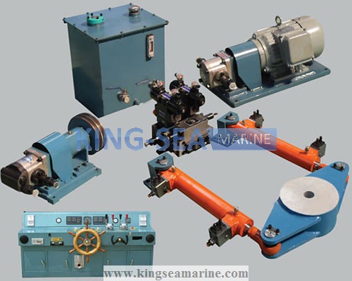
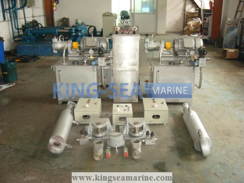
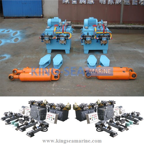
1. Features and Application
Synchronous Hydraulic Steering Gear adopts the electric-hydraulic linking control system, which overcomes the shortcomings by use of connecting rod or electric control alone, and it also can reduce the resistance differences between both rudders and sychronise the two rudders at same pace during the whole steering operation.
Synchronous Hydraulic Steering Gear has 24V electric operation, maneuvering wheel operation and emergency maneuering wheel operation, and is also equipped with power lost, lack phase, over loading, low oil level and filter choke light and audible alarm.
Synchronous Hydraulic Steering Gear fully comply with the regulations and requirments from the world's major classification societies, such as CCS,ZY,BV,ABS,etc. It is suitable for catamaran, open-body ship and board-body ship with nominal torque ranging from 5kN.m to 500kN.m.
2. Technical Specification:
Model
Norminal Torque
Max. Working
Safety Valve
Max. Rudder
Rudder Turning
KSEHS-2×5.0-20-SY
10
5.8
7.3
±35
20
KSEHS-2×10-20-SY
20
7.2
9
±35
20
KSEHS-2×15-20-SY
30
11.6
14.5
±35
20
KSEHS-2×20-20-SY
40
11.2
14
±35
20
KSEHS-2×25-20-SY
50
9.5
11.88
±35
20
KSEHS-2×30-20-SY
60
9.7
12.13
±35
20
KSEHS-2×35-21-SY
70
10.2
12.75
±35
20
KSEHS-2×40-20-SY
80
10.8
13.5
±35
20
KSEHS-2×50-20-SY
100
10.1
12.63
±35
20
KSEHS-2×63-20-SY
125
9.3
11.63
±35
20
KSEHS-2×75-20-SY
150
10.3
12.87
±35
20
KSEHS-2×80-20-SY
160
10.6
13.25
±35
20
KSEHS-2×100-20-SY
200
10.6
13.25
±35
20
3. Hydraulic System Principle Diagram
(kN.m)
Pressure (MPa)
Pressure (MPa)
Angle (o)
Time (s/65o)

Notes:
1) Clients shall indicate the numbers of rudder and the diameter of rudder stock during ordering;
2) The connecting rod used in the system shall be provided by clients;
3) If the ordered steering gear system requires the rudder turning time to be ≤12s or ≤28s, and the maximum rudder angle to be ±45 degree, the clients must indicate those technical parameters in the order contract;
4) We reserve the rights to revise or improve some parameters listed in this brochure without further notice.